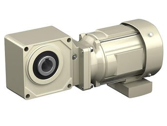
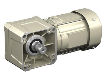
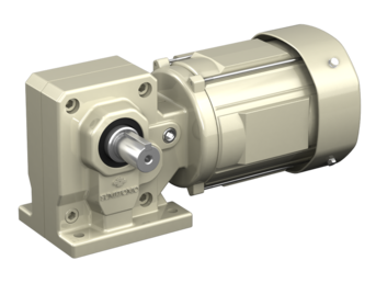
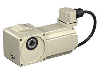
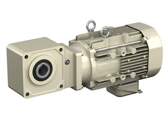
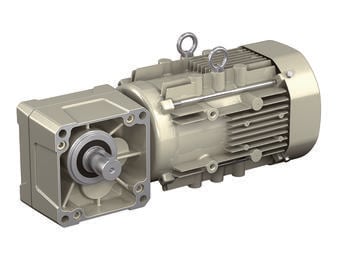
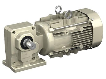
HYPONIC® Gearmotor
Right angle shaft gearmotor, with a motor range of 1/8 to 15 HP
- A wide range of choices (1/8 to 15 HP) to accommodate all types of uses.
- Modular design allows for multiple gearhead and motor combinations for increased service factor.
- A variety of industry packages and options are available, including grease lubrication, antibacterial coating, waterproofing and low temperature requirements.
| Output Shaft | Hollow shaft, Solid shaft |
| Output Shaft Direction(s) | Any Mounting Direction |
| Mounting Style | Shaft mount, Foot mount, Flange mount |
| Frame Size | 12 sizes |
| Reduction Ratio | 5:1 - 1440:1 |
| Capacity | 1/8 to 15 HP |
| Motor Types | Three phase, premium efficiency, high efficiency, for inverters, single phase, outdoors, waterproof, increased safety, compliant with overseas standards |
Product Features
CAD / Configure
Select your level of product detail:
Learn more about our CONFIGURATOR TOOL:
There are many accessories for use with the Helical Shaft Mount (HSM). Our patented Taper Grip Bushing is well suited for any application. A motor mount, backstop, torque arm, ABS belt guard, belts, breathers, sheaves and harsh duty seals are all accessor
Do you supply a torque arm? At what position should it be mounted? A torque arm assembly is offered as an option. The standard torque arm assembly and standard mounting positions are shown in the Appendix of our catalog.
What is the efficiency of a hypoid reducer?
A hypoid reducer is more efficient than the traditional worm gear reducer. The reason why a hypoid gear is more efficient than a worm gear is due mainly to two factors: gear tooth profile and the material it is made of. Hypoid gear is all-steel, while worm gear uses steel and a bronze wheel (that will wear down). Click here to learn more.
What is meant by load centering?
The reducer’s radial load capacities are calculated at the midpoint of the slow speed shaft extension. Radial load capacities decrease if the center of the load is moved farther from the reducer and the values obtained must be adjusted accordingly. Refer to the Special Load Guidelines section in the Appendix of our cagtalog for load location factors.
Should overhung load and thrust load be considered when making a selection?
Yes, loads imposed on the slow speed shaft will vary according to the method used to connect the shaft to the driven machine. Frequently, in addition to the torsional forces, radial (overhung) and thrust loads are applied to the slow speed shaft at the same time. For example, coupling connections normally involve torsional forces only. However, when power is transmitted through spur gears, belts, pulleys, or chains, both torsional and radial forces may be present. When driving through helical or bevel gears, all three conditions (torsional, radial, and thrust load) may be referred to the reducer shaft. The slow speed shaft and bearings must have sufficient strength to withstand these loads, and it is necessary to determine the allowable limits for each condition. The Special Load Guidelines section in the Appendix of our catalog explains how to calculate the overhung load (radial) applied to the output shaft.
What should be considered when connecting to the Hyponic® shaft?
When mounting a pulley, sprocket, or sheave, mount as close to the unit housing as possible; never mount beyond the midpoint of the shaft projection to avoid undue bearing load and shaft deflection. Never overtighten belts or chains. Careful and accurate installation is essential for best results and trouble-free operation. Before installing, the shafts should be checked to make sure they are parallel and level. After mounting, alignment should be checked with a string or straight edge held against the sides of the sprocket or pulley base. Couplings should be properly aligned to the limits specified by the manufacturer. Check alignment prior to initial startup on coupled Hyponic® units.
What is the rotation of the Hyponic shaft?
The direction of shaft rotation on Hyponic reducers varies according to frame size and ratio. Please refer to the Appendix in our catalog for specific data on the shaft rotation of various models.
What is the required tolerance of the shaft to be used on the Hyponic®?
Shaft tolerances will depend on the type of load and shock load of the application. Shaft tolerance recommendations are included in the Appendix of our catalog.
Do you supply a torque arm? At what position should it be mounted?
A torque arm assembly is offered as an option. The standard torque arm assembly and standard mounting positions are shown in the Appendix of our catalog.
What is the standard mounting of the Hyponic®?
The Hyponic® is standardly supplied as a shaft mount with a keyed hollow bore. Options are available for a solid shaft with feet and a flange mounting configuration. Since the Hyponic® is grease lubricated as standard, it can be mounted in any position
without modifications.
What are the thermal limitations of the Hyponic®?
The Hyponic® speed reducer, by virtue of its smooth, almost frictionless operation (unlike traditional helical gears), has a thermal rating that far exceeds its mechanical capacity and all but eliminates the conventional limitations due to heat.
